Click HERE to Choose the Right Storage heater model for you or contact 012-604 3731 formore details explanation.
| Heater Installation |
.jpg) |
SAFETY PRECAUTION This sign warns of serious injury, damage to property and potential death. Before operating, please read the following “Safety Precautions” carefully. |
||||||||||||
|
|
IMPORTANT
|
||||||||||||
- Select a suitable location for convenience of water and electrical supply as well as easier for future maintenance. Make sure the location is free from water splash.
- In case the water supply is from the water tank, the water heater should be connected to a booster pump (minimum 0.15 MPa / 1.5 bar), in order to have sufficient hot water flow.
-
For Horizontal Model (JH)
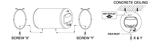
- Remove screw X and Y from the heater and position the mounting rings to the desired mounting position, according to the type of mounting position required (Refer figure A).
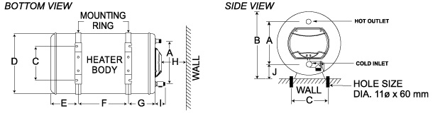
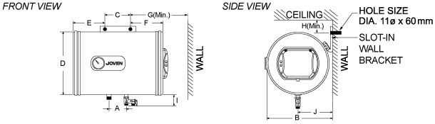
- Mark and drill 4 holes (Ø11mm X 60mm) with dimension C and F (Refer figure C).
- Insert the expansion bolts firmly to the holes and remove the hex nuts and washers.
-
Mount the mounting rings in position to the expansion bolts.
CAUTION
Ensure the inlet pipe is at the lower position (Refer figure A).
- Securely fasten the washers and hex nuts. Reinstall screw X and Y.
-
For Vertical Model (JVA)
- Mark and drill 2 holes (Ø11mm X 60mm) with dimension C and F (Refer figure C).
- Insert the expansion bolts firmly to the holes and remove the hex nuts and washers.
-
Mount the mounting bracket in position to the expansion bolts.
CAUTION
This appliance is designed for vertical mounting to the wall only.
- Securely fasten the washers and hex nuts.
-
For Horizontal Model (JHT)
- Refer to figure B, mark and drill 2 holes (ø11mm x 60mm depth) on the wall.
- Insert the expansion bolts firmly into the holes and remove the hex nuts and washers.
- Fix the wall bracket to the expansion bolts and securely fasten the washers and hex nuts.
- Carefully hang the mounting bracket of the heater to the wall bracket on the wall.
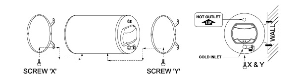
FIGURE A : MOUNTING RINGS POSITION FOR HORIZONTAL MODELS
TOP MOUNTING (ON CEILING OR FLOOR)
LEFT HAND SIDE MOUNTING (ON WALL)
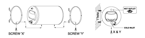
RIGHT HAND SIDE MOUNTING (ON WALL)
HANGING MOUNTING (ON CONCRETE CEILING)
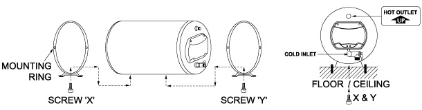
FIGURE B : SINGLE SLOT-IN WALL BRACKET FOR HORIZONTAL MODELS
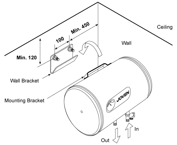
FIGURE C : INSTALLATION DIMENSIONS
JH MODEL
JVA MODEL
.jpg)
JHT MODEL
| SPECIFICATIONS | |||||||||||||
| Model | Tank Capacity Litres (Imp. Gals) | Dimensions (mm) |
Approx. Wt. Kgs (Empty / Full) |
||||||||||
| A | B | C | D | E | F | G | H | I | J | ||||
| JH 15 | 15 (3.3) | 260 | 405 | 265 | 381 | 96 | 70 | 96 | 350 | 65 | 92 | 10 / 25 | |
| JH 25 | 25 (5.5) | 260 | 405 | 265 | 381 | 121 | 150 | 121 | 350 | 65 | 92 | 12 / 37 | |
| JH 35 | 35 (7.7) | 260 | 405 | 265 | 381 | 121 | 269 | 121 | 350 | 65 | 92 | 14 / 49 | |
| JH 38 | 38 (8.4) | 260 | 405 | 265 | 381 | 121 | 304 | 121 | 350 | 65 | 92 | 15 / 53 | |
| JH 50 | 50 (11.0) | 260 | 405 | 265 | 381 | 121 | 438 | 121 | 350 | 65 | 92 | 17 / 67 | |
| JH 56 | 56 (12.3) | 260 | 405 | 265 | 381 | 121 | 508 | 121 | 350 | 65 | 92 | 18 / 74 | |
| JH 68 | 68 (15.0) | 260 | 405 | 265 | 381 | 121 | 648 | 121 | 350 | 65 | 92 | 20 / 88 | |
| JH 91 | 91 (20.0) | 260 | 405 | 265 | 381 | 121 | 914 | 121 | 350 | 65 | 92 | 25 / 116 | |
| JVA 25 | 25 (5.5) | 100 | 393 | 217 | 372 | 121 | 271 | - | 316 | 65 | 77 | 12 / 37 | |
| JVA 35 | 35 (7.7) | 100 | 393 | 217 | 372 | 121 | 390 | - | 316 | 65 | 77 | 14 / 49 | |
| JVA 50 | 50 (11.0) | 100 | 393 | 217 | 372 | 121 | 559 | - | 316 | 65 | 77 | 17 / 67 | |
| JHT 35 | 35 (7.7) | 100 | 385 | 100 | 381 | 206 | 206 | 450 | 120 | 58 | 170 | 14 / 49 | |
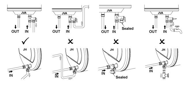
| Plumbing Connection |
|
|||||||
.jpg)
|
A. Cold Water Inlet from Main Supply / Water Tank B. Control Valve (Not Included) C. Single or Double Check Valve (Not Included) D. Pressure Relief Valve |
E. Drain Valve (Must Not Be Closed / Blocked) F. Overflow Pipe to Drain or Floor Trap G. Hot Water Outlet to Mixer Tap |
|
|||||||
|
|
|||||||
|
A. Cold Water Inlet from Main Supply / Water Tank B. Control Valve (Not Included) C. Single or Double Check Valve (Not Included) D. Pressure Relief Valve |
|||||||
|
TO FILL HEATER TANK
|
|||||||
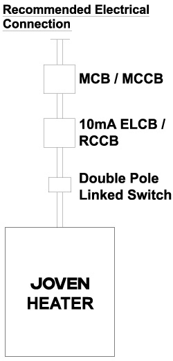
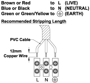
| Electrical Connection |
|
|
IMPORTANT
|
|||||
Table : Electrical Loading Table
| HEATER ELECTRICAL LOADING | MINIMUM CONDUCTOR SIZE | ||||
|
Voltage (Va.c.) |
Power (kW) |
Conductor Size (mm2) | |||
| 220 to 240 | 1.37 to 1.63 | 2.0 | |||
| 2.50 to 3.00 | 2.5 | ||||
 |
|
|||||
| Operating Procedure |
|
|
|
|
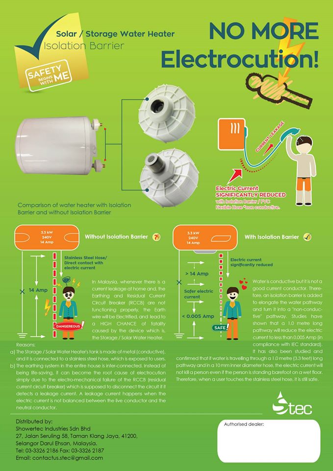
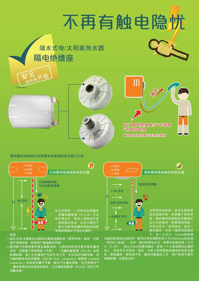
The first operation and heating of the appliance must be observed by the installing technician after water and electrical connection have been made and heater tank filled with water, before switching on the electrical supply. Installation of storage water heater - Isolation barrier - ultimate safety for storage water heater - hot water piping installation - Stainless steel stopcock - Safety valve - Drain Pipes - Check Valve - Not Included Wiring Point - 1 year installation warranty |
|